Products

Multi Rake Bar Screen
Multi rake bar screen is a mechanically cleaning screen which is installed in the inlet works of treatment plants, pumping stations and water inlet structures ( CHANNEL ) to capture solid materials as a result to reduce load of down stream processes and to the downstream equipment. Clogging possibility is minimized by using number of rakes which are lined with endless chain which driven by motor and gearbox Screen opening can be manufactured from 5 mm to 50 mm, install in channel width from 400 mm to 2500mm and depth up to 10 meter typically setting angle between 70 to 85 degrees or vertical . Choice of 304 or 316 Stainless steel or MS construction including drive sprocket and chain self-supporting integral frames with engineered for maximum strength key to stand deep channel applications. Full automatic operations.
Deep rake tooth penetration to eliminate blinding while operating at slower speed promoting longer rake and bar rake life.
Features
• Bar opening screen 5 up to 50 mm
• Easy & fast replacement of filtering media
• High screen efficiency
• Low power required
• Very less maintenance
• Inclination 70 degree or vertical
• Used in municipal WWTP
• Used in industrial WTP like textile, food, chemical, tannery, and other industries.
• Used in CETP

| Model | Opening 2mm | Opening 5mm | Power kw |
|---|---|---|---|
| RD5X1 | 25 m3/h | 45 m3/h | 0.37 |
| RD6X1 | 55 m3/h | 80 m3/h | 0.55 |
| RD6X2 | 70 m3/h | 100m3/h | 0.75 |
Rotating Drum Fine Screen
The rotating drum fine screen is used for filtration in ETP /STP.
Rotating drum fine screen consist of filtration media available from 1 mm to 5 mm which rotates. Rotating drum is supported by suitable shaft and is operated by geared motor. The effluent entered in the drum consist screw flight which helps solid to move from one end to other. filtration takes from inside to outside, and also provide brush arrangement from cleaning filtration media also provide the backwash flushing arrangement from outside for cleaning filtration media. Provided bottom tank with nozzle to collect filtrate. Provided hopper to guide the solid to fall down on floor/bin. Equipment is completely closed.
Features
• Continues Operation
• Easy / Line installation
• Less space required
• Low power required
• Very less maintenance
• Suitable for MBR application
Rotating Arm Coarse & Fine Screen
The rotating arm parabolic fine screen is used for filtration in ETP /STP.
Rotating arm fine screen consists of filtration media available from 2 mm to 10 mm in hole and bar spacing which arm rotates consist of brush or comb which cleans the filtration media and screen is collected in bin. Rotating arm is supported by suitable bearing shaft and is operated by geared motor. The effluent entered in the channel consist of screen filtration takes from inside to outside, Equipment is completely closed by canopy.
Features
• Continues Operation
• Easy / Channel installation
• Less space required
• Low power required
• Very less maintenance
| Model | Max Flow m3/hr |
|---|---|
| DT4X1 | Up to 20 |
| DT6X1 | Up to 30 |
| DT4X2 | Up to 40 |
| DT6X2 | Up to 60 |
| DT10 X2 | Up to 140 |
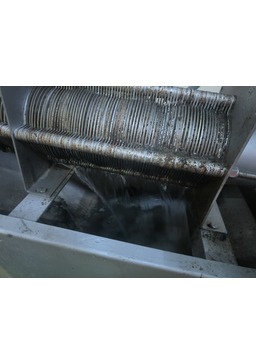
Sludge / Rotary Drum Thickener
Drum thickener in installed prior to digestion or dewatering process and can deal with biological, chemical, mixed sludge throughput ranges from 5 m3/hr to 150 m3/hr. This thickening system enables you to reduce your sludge volume around 90%.
The flocculated sludge entered in the drum where a screw which conveys the sludge from one end to another end simultaneously filtration will takes place from inside to outside through drum, drum which form from filter cloth made from polyester material, as a result gradually increase the consistency of sludge and allows free water to fall down in bottom tank. Also a backwash system cleans the filter cloth from outside to inside during operation. Degree of thickening can be controlled by reducing or increasing of RPM of drum.
Features
• Small footprint
• Easy to installation
• Very low power consumption
• Low polymer consumption
• Very less & Easy maintenance
• Less supervision
• Separation efficiency more than 98%
• Less supervision
• Less wear
Sludge Dewatering Belt Filter Press
A Belt Filter Press is a sludge dewatering device that applies mechanical pressure to chemically conditioned slurry, which is sandwiched between two (2) tensioned belts, by passing those belts through a serpentine of decreasing diameter rolls. The machine can actually be divided into three (3) zones: gravity zone, where free draining water is drained by gravity through a porous belt; wedge zone, where the solids are prepared for pressure application; and pressure zone, where medium, then high pressure is applied to the conditioned solids.
Features
• High Dryness and solid capture rate belt filter press
• Advanced slurry distribution unit
• Reliable and stable in operation
• Longer service time
• Low energy consumption
• Wide range application
• Easy to operate and maintenance
• Compact structure, small space to install
• Automatic operation, reducing labor cost and intensity
| Model | BELT WIDTH MM | ELECTRIC LOAD | DIMENSIONS LxWxH | AIR REQUIREMENT | BACKWASH WATER |
|---|---|---|---|---|---|
| BFP 6 | 600 | 0.5 | 3.9x1.0x1.3 | 1 m3/hr | 4 m3/hr |
| BFP 12 | 1200 | 1.0 | 3.9x1.6x1.3 | 1 m3/hr | 6 m3/hr |
| BFP 15 | 1500 | 1.5 | 3.9x1.9x1.3 | 1 m3/h | 9 m3/hr |
| BFP 18 | 1800 | 1.5 | 3.9x2.2x1.3 | 1 m3/h | 10 m3/hr |
| BFP 22 | 2200 | 1.5 | 3.9x2.6x1.3 | 1 m3/h | 12 m3/hr |
| BFP 26 | 2600 | 2.0 | 3.9x3.0x1.3 | 1 m3/h | 14 m3/hr |

| Model | No of Bag | Sludge DS kg/day |
|---|---|---|
| 1BDU | 1 | 20 |
| 2BDU | 2 | 50 |
| 3BDU | 3 | 90 |
| 4BDU | 4 | 110 |
| 6BDU | 6 | 180 |
Bag Sludge Dewatering System
Bag sludge dewatering unit is used in ETP/STP for dewatering of sludge.
The sludge is fed to the flocculator installed on the dewatering equipment. At the same time, liquid poly is mixed in the flocculator. As a result, well flocculated sludge is fed to bags for approximately 2 to 3 hours, then kept idle for another 4 to 5 hours for further dripping. The cycle depends on sludge characteristics. Filtrate is collected in the bottom tank and drained via nozzle. After operation, bags are removed using a trolley, sealed, and kept in open space for drying. Dry solids up to 90% can be achieved in 4-5 days during summer.
Features
• Because of closed bag less odor
• Easy installation
• Less space required
• Low power required
• Very less maintenance
• Separation efficiency more than 95%
• Less man power

Decanter Centrifuge
DECANTER CENTRIFUGE is used in ETP/STP for dewatering of sludge.
A centrifuge decanter consists of a solid cylindrical bowl rotating at high speed, a scroll rotating at a slightly different speed, and a drive group to control this difference. The liquid is fed to the distribution room and accelerated into the bowl. Centrifugal force separates the solids to the bowl wall, and clarified liquid exits through adjustable plates. It is widely used for separation, dewatering, thickening, classification, and extraction.
Features
• Continues Operation design
• Easy installation
• Easy operation and maintenance
• MOC: SS 304, SS 316, Duplex steel
• Less man power
• Spares easily available
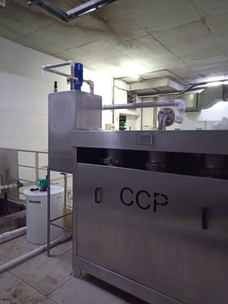
Screw Filter Press/ Multidisc Screw Press
SCREW PRESS is used in ETP/STP for dewatering of sludge.
The CCP Screw Press is a unique product That offers many advantages over current sludge management practices. The key to the process is the “dewatering drum.” This drum can achieve both thickening and pressing (dewatering) of the sludge in a single, compact operation. Thus the CCP Screw Press can take sludge as dilute as 0.2% to 5% solids directly from a treatment process, such as bottom of clarifier, and produce a cake of over 20 to 35% solids. depend on sludge characteristic. Separate thickening, storage, and conditioning processes are eliminated. In addition, it eliminate operators, continuous use of wash water, and high power consumption.
Features
• Best suitable for oily sludge
• Continues operation design
• Easy installation
• Less space required
• Very low power required
• MOC : SS 304, SS 316,
• Less man power
• Spares easily available
• Very less backwash water
• Easy operation
• Easy maintenance
• Low noise
• Low vibration
| Models | Machine Size(mm) LxWxH | Machine Output Capacity (Kg.Ds/h) (For Sludge Concentration From 0.2%-10% respectively) |
Machine Tool Power(kW) |
|---|---|---|---|
| CCP-101 | 1850x740x1040 | 3-22 | 0.24 |
| CCP-131 | 2000x785x1080 | 6-37 | 0.24 |
| CCP-201 | 2510x900x1300 | 13-69 | 0.37 |
| CCP-202 | 2560x1050x1300 | 26-149 | 1.49 |
| CCP-301 | 3330x1005x1760 | 30-179 | 1.3 |
| CCP-302 | 3530x1290x1760 | 60-310 | 2.25 |
| CCP-303 | 3680x1620x1760 | 90-600 | 3.35 |
| CCP-304 | 3830x2010x1760 | 120-800 | 4.1 |
| CCP-351 | 4040x1160x2130 | 60-310 | 1.85 |
| CCP-352 | 4390x1650x2130 | 120-800 | 3.3 |
| CCP-353 | 4530x1980x2130 | 180-1200 | 4.8 |
| CCP-354 | 4750x2715x2130 | 240-1500 | 5.9 |
| CCP-401 | 4680x1345x2100 | 67-540 | 2.6 |
| CCP-402 | 4960x1760x2100 | 133-1300 | 4.5 |
| CCP-403 | 5010x2460x2100 | 200-1700 | 6.7 |
| CCP-404 | 5160x3160x2100 | 267-2100 | 8.2 |

Sludge Dryer/Paddle Dryer
PADDLE DRYER is used in ETP/STP/MUNICIPAL/INDUSTRIAL for of sludge drying.
The twin shaft design of the CCP paddle dryer ensure a perfect mixing in a radial direction of the shaft where as the transportation of the product through machine is achieved by gravity which results from an inclination of the machine due to its very narrow particles residence time distribution, the CCP paddle dryer is often used as a continues reactor where heat treatment can be combined with a time –depending reaction in a fully continues process The machine has a heated through, containing rotating heated paddle shaft. Specially shaped paddle are designed for maximum heat transfer. This result in an excellent control of the temperature of the product and enable a uniform product quality at the outlet side the product moves out of the machine via an adjustable overflow weir.
Features
• Reduction in waste disposal
• High energy transfer efficiency
• Self-cleaning mechanism
• Less foot-print
• Simple working principle
• Very low power required
• MOC : SS 304, SS 316,
• Less man power
• Spares easily available
• Easy operation
• Easy maintenance
• Longer operating life

Technical Specifications For 23 Plates :-
| Description For Zero Holdup | Specifications |
|---|---|
| Size | 18"DIA With 23 Plates |
| Design Pressure | 6 KG/CM2 |
| Filtration Area | 3.49 M2 |
| Cake Holding Cap | 120 Ltr |
| Output Ltr/Hr | 5500 Ltr |
CCP Zero Hold Up Filter Press Machine
Structural Specifications :-
| Description For Zero Holdup | Specifications |
|---|---|
| Shel | 3 MM SS |
| Top Gusket | Silicon |
| Keybolt/Wingnut/Pin | 10 NOS |
| Top Lid Cover | 3MM |
| Pressure Gauge | 0 TO 7 KG-SS |
| Air Vent Valve | 3/8 BSP |
| Bottom Plate | 16 MM |
| Pressure Bush Cup 60mm dia | 23 NOS |
| Filter Plates 18"DIA With Ring 25mm ht | 23 NOS |
| Filter Sieves | 16 swg 24 NOS |
| Bottom Filter Plate 15 MM | 01 NO |
| Side Tie Rods 5/8 bsw | 06 NOS |
| Centre Rod | 01 NO |
| Bottom Washer | 01 NOS SILICON |
| Flange Washer | 02 NOS SILICON |
| Outlet Ball Valve | 1.5" TC VALVE |
Details Of PUMP (SWASTIK Make OR ALFA LAWAL Make):-
| Description | Specifications |
|---|---|
| Head | 6 mtr long |
| Inlet & Outlet | 1.5"TC END MOC |
| All Contact Parts | SS 316L Quality |
| Non Contact Parts | SS 304 |
| SEAL- as per swastik | std design & std size |
| Description | Specification |
|---|---|
| Motor | 3 HP- ABB- NONFLP 2800 RPM 3 PHASE |
| ON/OFF Push Button | Push Button |
| Working Press | 0-3 kg/cm2 |
| Trolley | SS 304 & SS /PU Wheel with SS handle |

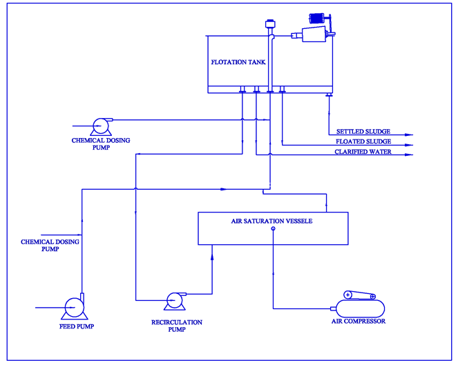
Main Component :-
FLOATATION TANK
SKIMMING DEVICE
AIR SATURATION VESSEL
RECIRCULATION PUMP
FEED PUMP
CHEMICAL DOSING PUMP
AiroDAF Clarifier Available Models :-
Circular :- 4 m3/hr to 1000 m3/hr
Rectangular :- 4 m3/hr to 200 m3/hr
Dissolved Air Flotation Unit/ AiroDAF Clarifier
Airo-Dissolved air flotation (AiroDAF) is water treatment equipment that clarifies wastewater (or other waters) by the removal of suspended matter such as oil or solids. The removal is achieved by dissolving air in the water or wastewater under pressure and then releasing the air at atmospheric pressure in a flotation tank or basin. The released air forms tiny bubbles which adhere to the suspended matter causing the suspended matter to float to the surface of the water where it may then be removed by a skimming device.Dissolved air flotation is very widely used in treating the industrial wastewater effluents from oil refineries, petrochemical and chemical plants, natural gas processing plants, dairy industry, automobile industry, food industry, paper mills, general water treatment and similar industrial facilities. A very similar process known as induced gas flotation is also used for wastewater treatment.
Process Description :-
The feed water to the AiroDAF float tank is often (but not always) dosed with a coagulant to coagulate the colloidal particles and/or a flocculants to conglomerate the particles into bigger clusters.A portion of the clarified effluent water leaving the Airo-DAF tank is pumped into a small pressure vessel (called the Air Saturation Vessel) into which compressed air is also introduced. This results in saturating the pressurized effluent water with air. The air-saturated water stream is recycled to the inlet of the float tank and flows through a pressure reduction valve just as it enters the inlet of the float tank, which results in the air being released in the form of tiny bubbles. Bubbles form at nucleation sites on the surface of the suspended particles, adhering to the particles. As more bubbles form, the lift from the bubbles eventually overcomes the force of gravity. This causes the suspended matter to float to the surface where it forms a froth layer which is then removed by a skimmer. The froth-free water exits the float tank as the clarified effluent from the DAF unit.
Features
• Very low retention time 3-4 minutes
• Small foot print
• Easy installation
• Ready to use
• Low chemical consumption
• Sludge consistence more than 1%
• Efficiency 95-98%
• Very low startup time
• Pre-fabricated unit
• Easy to relocate
• Civil cost very low
Industry
• Automobile
• Dairy
• Meat processing industry
• Paper and pulp industry
• Tannery industry
• Textile industry
• Pharmaceutical industry
• Fish processing industry
• Cosmetic industry
• Paint shop
• Municipal STP
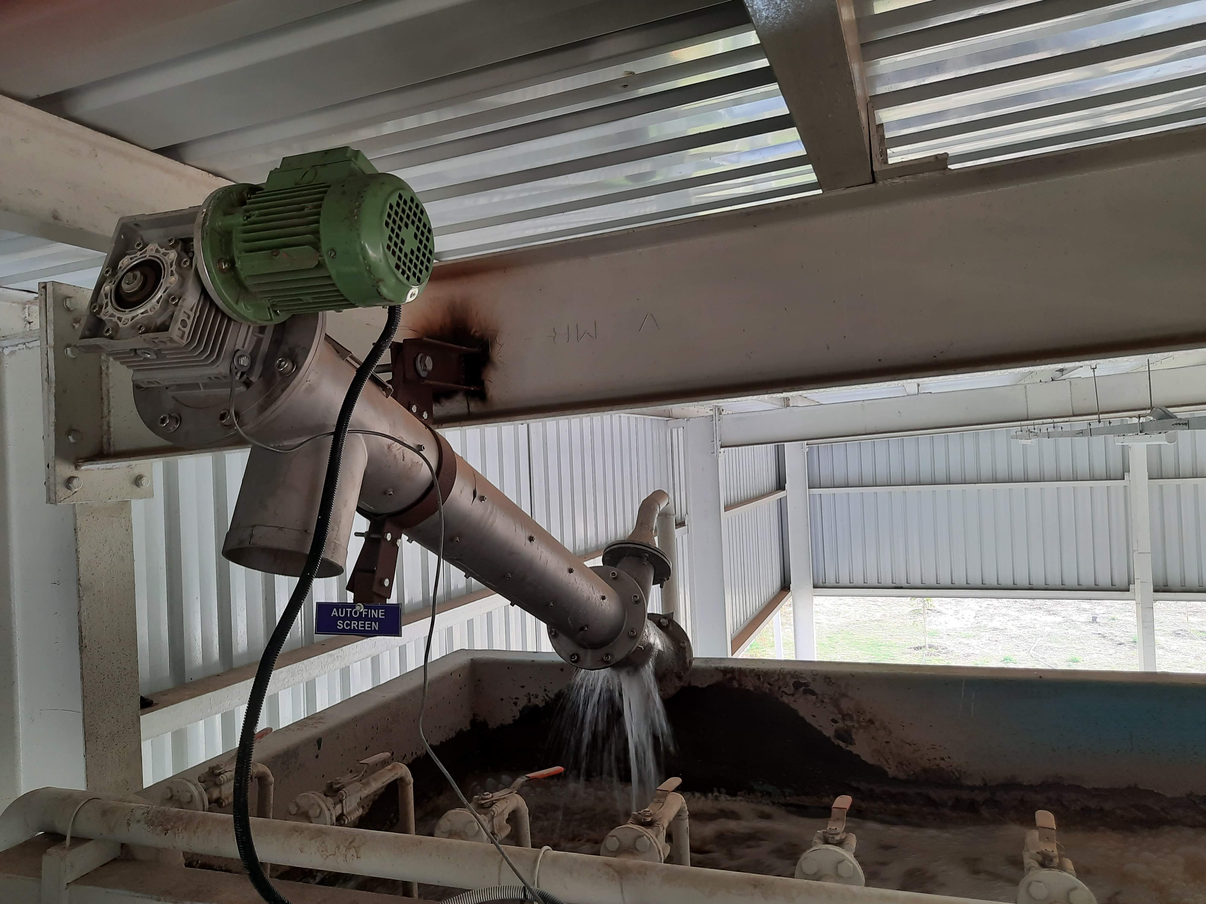
Fine Screw Screen
The fine screw screen will be manufactured in SS304 or SS316 with an hole opening of 2 mm to 5 mm punched hole. The Rotating screw will have a spiral welded to it with brush on lower end to clean the filtration media and suitably so as to convey the suspended solids in the forward direction. Moc of screw is carbon steel hot deep galvanized or Epoxy painted. as shaft rotates brushes wipe the solids from perforated area and travel to the outlet of the screens Simultaneously clean the perforated filter media.
System is designed to remove Oil droplet size of upto 50 micron.
Parts
• Continues Operation
• Capacity up to 100 m3/hr.
• Bar Spacing/ Hole opening from 2 mm to 6 mm
• Available in SS304 & SS316
• Easy / Channel installation
• Less space required
• Low power required
• Very less maintenance

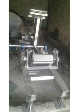
Screw Press Cow Dung Dewatering Machine
Working Principles :-
1.When the cow manure dewater machine is working,the dung slurry pump will pump the animal manure into the main body of the cow manure dewater machine.
2.In the body of the cow manure dewater machine,there are a screw and screen. As the cow manure enter into the cow manure dewater machine,the screw will pull the manure from the left to the right at the speed of 45r/min.
3.When cow manure are transported the right of cow manure dewater machine,the screen will continuous press the manure to dewater the manure.
4.The manure is dewatered and discharged by the cow manure dewater machine.
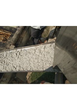
Application :-
The moisture of the manure can reach as less as 40%,you can not press any water by hand.
1.The dewatered manure can be enpacked at once,after fermenting,it can be directly used as farmyard manure.
2.The dewater manure can be deep processed as the material of industrial fertilizer.
3.The dewater manure can be made as feed in the fishery industry.
Performance & Technical Features-Benefits
• Compliant with a wide range of materials in different throughput rates
• Optimized feeding thanks to compensator tank
• Outlet diaphragm for solids manufactured from anti-wear engineering polymer: cost saving in spare parts
• Self-balanced pressure at the solids outlet:steady and safe operation
• Simple operation and cost saving in spare parts
• Continuous operation
• Quick return on investment
Function
This Cattle Farming Equipment is a solids-liquid separating machine including a screw conveyor. Using both principles of separation,by gravity and by mechanical pressing,the machine is designed to separate the liquid phase from the solid phase in a wide range of substances such as sludge, sewage, manure, solids-liquid mixtures, vegetables, processing waste and others, where the percentage of liquid inside the solid may be considerably different.
The separated solid and liquid phases can be handled in an easier and cheaper way. In some sectors this can even become a source of income.
Operation
The machine receives the material to be separated and conveys it using the screw conveyor inside the separator casing.The liquid phase is separated through the mesh of the cylindrical screen which encloses the screw conveyor. Along its path toward the exit, the material gradually separates progressively the less linked liquid and then the more strongly linked liquid until a plug of almost dry material has formed before the outlet. The plugis continuously expelled through the outlet diaphragm. The machine will automatically find its balance of squeezing force depending on the material. Consequently, it can be used for a wide range of materials without the need for any manual adjustments.
The Parameter Data Of Solid-Liquid Separator
| Model | Motor | Screen size | Manure pen depth | Capacity |
|---|---|---|---|---|
| CCP-180 | 4kw | 0.3mm,0.5mm | 0.7-1.5m | 3-5t/h |
| CCP-200 | 4kw | 0.3mm,0.5mm | 0.7-1.5m | 5-7t/h |
| CCP-260 | 5kw | 0.3mm,0.5mm | 0.7-1.5m | 10-12t/h |
| CCP-280 | 5.5kw | 0.3mm,0.5mm | 0.7-1.5m | 15-17t/h |
Brief Introduction Of Solid Liquid Separator :-
Solid liquid separator is used for dehydrating processing of the poultry dung. It can separate the solid and liquid organic fertilizer of all kinds of poultry dung after extruding and dehydrating, like chicken, cow, pig, duck, sheep and so on.
This machine used to reduce the water content of animal dung.
The solid content in the raw material can be 30-40%, and the moisture of final product is about 40%, you can’t press out any water by hands.
Features Of The Solid Liquid Separator :-
1. Extrusion spiral:twins wing blades,made of stainless steel , corrosion resisting and wear-resisting because of the special processing.
2. Filter sieve: made of stainless steel, precision processing;Using different specifications sieve
3. The solid dung is easy to transport after separating.
4. The solid can also used for making the organic fertilizer,fuel etc.
Application Scope Of The Solid Liquid Separator :-
1. Animal wastes, such as pig manure, cow dung, poultry dung, horse excrement and other kinds of animal manure
2. Biogas slurry, sludge gas and biogas fermentative residue
3. Manioc waste, tea slag, sweet potato waste, maize pulp, bagasse, medicine dregs, wpp d pulp fiber, paper pulp fiber, bean dregs, coffee grounds and so on
4. Any kinds of solid liquid separation
Technical Data Of The Solid Liquid Separator
| Model | CCP-I | CCP-II | CCP-III |
|---|---|---|---|
| Power(KW) | 4 | 5 | 7.5 |
| Capacity(M3/H) | 5-9 | 13-16 | 15-25 |
| Moisture before treatment | >=65% | >=65% | - |
| Moisture after treatment | 40%-50% | 40%-50% | 40%-50% |
| Material of inside | SS304 | SS304 | SS304 |
| Material of outer | Cast iron | Cast iron | Cast iron |
| Water pump | 3KW | 3KW | 3KW |
| Water pipes | 8M | 8M | 8M |
| Water seal | 2 sets | 2 sets | 2 sets |
| Cabinet | 1 set | 1 set | 1 set |
| Outsize | 1900*750*1680 | 1900*780*1680 | 1900*820*1680 |
| Weight | 300 KG | 450 KG | 650 KG |

| Model | Capacity m3/hr. |
|---|---|
| FLCR25 | 25 |
| FLCR70 | 70 |
| FLCR100 | 70 |
| FLCR150 | 150 |
| FLCR200 | 200 |
| FLCR300 | 300 |
| FLCR800 | 800 |
| FLCR1200 | 1200 |
FLOCCULATOR
To get good ferformance from sludge dewatering machine the sludge has to be conditioned with suitable polyelectrolyte/ flocculant by using technology of bottom inlet and top outlet it has been forund that a slow agitation tank with a residence time up to 3 to 4 minutes is normally sufficient to do a good job of flocculation after the mixing of sludge and polyelectrolyte strong large size flocks will be obtained which are fed to the dewatering machine available size from 20 lit to 1500 lit.
Features
• Low maintenance cost
• Low operating cost
• MOC : SS304 & SS316
• Available in rectangle and cylindrical shapes
• Precise control of the poly dilution process
• Reduce wastage of polyelectrolyte.
• Ease and comfortable in operation
• Minimum operation interference
• Minimum operation interference
• Precise control of the poly dilution process
Feature:
• Continues operation design
• Easy installation.
• Less space required.
• Very low power required.
• MOC : SS 304, SS 316.
• Less man power.
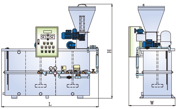
AUTOMATIC POLY PREPARATION UNIT
The automatic polyelectrolyte preparation and dosing unit consists of a rectangular tank divided into three compartments. The first compartment, for mixing Powdered polyelectrolyte with water polyelectrolyte loading hopper installed on top of the machine, micro-screw batcher and relevant variable speed drive ( VFD) , fast stirrer for the polyelectrolyte mixing, inflow system for the dilution water and relevant solenoid valve, flow meter; the second compartment, for the polyelectrolyte mixture ageing, is equipped with slow stirrer and bottom suction and drain system. The third compartment, for ageing and storage, is used for the mixture storing and is provided with slow stirrer and suction and delivery system for the polyelectrolyte solution.it also provided low and high level sensor to automatic start and stop of water flow and powder polyelectrolyte. Every stirrer has impellers fitted on its shaft, each one with four sloping blades. The polyelectrolyte preparation occurs automatically: in fact, once the concentration (from 0.05% to 0.5% by weight) has been established, the dosing of dilution water and polyelectrolyte starts automatically. The solution at the automatic polyelectrolyte preparation unit outlet can be further diluted in the network, if required. The preparation unit is provided with alarms activated by the failure of the dosing screw or shortage of dilution water, insufficient level of polyelectrolyte in the hopper, faulty operation of the stirrer. The standard construction is in stainless steel.
Applications as
• Treatment of drinking water and water for industrial processes.
• Treatment of sludge, to improve the performance of centrifuges and filter press.
• Industrial Processes in paper mills, chemical industry, petrochemical, treatment of minerals, canning, etc.
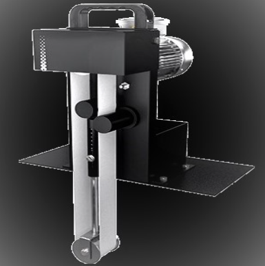
BELT OIL SKIMMER
A belt skimmer is a very simple product to remove the floating oil. A belt skimmer is mounted on tank tops. The unit consists of two (2) pulleys. Care is taken that the bottom pulley is below fluid surface level. The top pulley is connected to a geared drive. An endless belt of polyurethane material rotates on the pulleys. Bottom pulley has a self-tensioning arrangement to compensate expansion of belt over time. Fluid flows slowly over the belt leaving the floating oil on the surface of the belt. The belt scrapes through a pair of nylon scarpers near the top pulley. The scraped fluid is collected a tank. The separator tank is specially design with adjustable baffles. This separates the additional water content and diverts it back to the main tank.
Applications as
• Small mounting and operating area.
• Easily hand carried from tank to tank.
• Easily mounted on a flat surface.
• Belt and wipers impervious to oils and fuels
• High temperature capability.
• Customized belt lengths and materials.
• Fast cleaning with minimal maintenance.
| Model | Opening 2 mm to 8 mm |
|---|---|
| HDRAS500 | 20 m3/h to 100 m3/h |
| HDRAS1050 | 75 m3/h to 175 m3/h |
| HDRAS1600 | 100 m3/h to 300m3/h |
HALF DRUM ROTATING ARM/BRUSH SCREEN
The Half Drum rotating arm/brush fine screen is used for filtration in ETP /STP Half Drum Rotating arm fine screen consists of filtration media available from 2 mm to 10 mm in hole and bar spacing which arm rotates consist of brush or comb which cleans the filtration media and screen is collected in bin. Rotating arm is supported by suitable bearing shaft and is operated by geared motor. The effluent entered in the channel consist of screen filtration takes from inside to outside, Equipment is completely closed by canopy.
Features
• Continues Operation
• Capacity up to 400 m3/hr.
• Bar Spacing/ Hole opening from 2 mm to 8 mm
• Available in SS304 & SS316
• Easy / Channel installation
• Less space required.
• Low power required
• Very less maintenance